
Update: Last time we were in mini-ville I had dribbled river rocks on to the luan plywood foundation - looked good until they started falling off. Apparently the foundation warped & when I weighed it down some of the rocks didn't like the change & popped off! Next time I will mix glue into the Water Putty.
I re-did the foundation in a textured finish, in a warm grey & used the 1st porch I made. We decorated this 'facade thing' as a Xmas display for the local hospital & someone actually bought it?!
So I think I'll stay away from decorating for awhile & concentrate on design & construction of dollhouse shells!
New Project
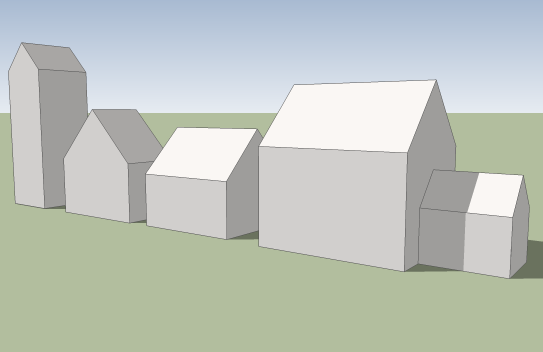 |
| Keeping the 45 degree pitch and staying within the size parameters there is still quite bit of variety. The drawing on the right has an addition using the same system. The addition could be attached to the front, but if its too tall then I would have to get into roof angles - not ready for that! |
 |
The possibilities are endless...
the kit builder would add their own components: windows, doors, shingles etc., including a porch & a couple of dormers in the above example.
|
I'm going back to my mat board & stick design as the luan plywood is problematic. I'm currently building all the jigs for the connectors I'll need. I liked the sliding dovetail joint but found it difficult to make so I've come up with a simpler design.
The dollhouse is stick built with either 1/16" mat board as the skin. The finished walls are 3/8", but I made the floors 5/8" thick as I thought they needed to be bit more beefy.
My idea is that I build the outer frame & glue the mat board to the exterior. Then the customer or 'kit builder' glues on the precut studs, joists & rafters & with a craft knife cuts out all the openings. This allows total freedom to place doors, windows, skylights, etc. whatever size or style & wherever desired. And two simple hand tools: a craft or utility knife & a razor saw w/miter box.
The walls, floors & roof can be assembled/disassembled in minutes. Also, I think I've come up with an easy way to electrify the dollhouse using a circuit board & computer ribbon cables & connectors. See below:
 |
| Ribbon wire plugged into circuit board, other end cut off & attached to wall wiring. |
 |
Contact happens between the floor joist &
floor support where the bronze bands are wrapped or pinned?
|
House Rules? This dollhouse building system allows the kit builder to choose the size of the house within the following parameters:
- Rectangular or square floor plan, no pop outs, dormers, etc. Although commercial dormers, bay windows, etc. can be added. And I think I could easily design additions to the gable side(s) using the same system.
- Gable style 'A' roof with a 45° pitch. Most commercial dormers I believe are 45°. I may add 30° & 60° pitch in the future? 30/60 adds gambrel & mansard roofs!
- Maximum interior dimensions: 15-1/2"d x 19-1/2"w x 20-1/8"h. Why these dimensions? Because I'm buying 16" x 20" mat board by the case from Golden State Art - A1 company, good prices & free shipping! What's not to like...
 |
| The grey grid shows the dimensions of the strip wood used for all the connectors. The color coded outlines show the quantities of that part. The red parts are used on the open eaves house in the upper-right corner (typical open back style dollhouse) & the cyan parts are for the open gable style house in the bottom-left corner. The purple parts are used on both houses. |
Construction from the ground up:
 |
| (4) Base plates |
 |
| (8) Corner posts |
 |
| (8) Floor supports |
 |
| (1) Front roof connector |
 |
| (4) Gable end rafters |
 |
| (4) Roof end connectors |
 |
| Cross members: (2) Ridge connectors & spline; (2) [Back cutout frame; Front eaves frame] |
 |
| (8) T-joists & (2) Back sills |
 |
| Roof edge trim |
 |
| Exterior mat board |
 |
| The kit builder adds precut studs. The studs would be positioned around window & door openings. Joists around stairwells & rafters around skylights or chimneys, etc. |
 |
Then the kit builder adds the interior mat board.
Obviously someone forgot to cut out the openings for this house - hmmm jail house?
|
 |
| Here's a picture of the framing for around a window. The vertical studs just need to be moved in to the edges of the window frame. The horizontal pieces need to be cut to the window's 'fits opening width'. Then the studs are glued to the mat board, dried, then the mat board is trimmed using the frame as guide. |
 |
| Then the interior mat board is glued in place, dried, then the interior mat board is trimmed from the outside using the same method as above. |
Assembled in sections:
 |
| Left wall |
 |
Place the front wall to the corner connector of the left wall then insert locking spline.
See detail below:
(click to enlarge)
|

 |
| Repeat with right wall. |
 |
| Slide in floors. |
 |
| Lock back to sides with splines. |
 |
| Add front roof. |
 |
| ...and finally add back roof. The front & back roof halves hook in near the eaves then they are locked together at the peak / ridge in the same way as the walls. The sections do not need to be glued together. The house can be disassembled in reverse order. This allows the dollhouse to be easily decorated, stored or mailed. |
THE JIGS: Quick change jigs attach to table saw
 |
| Jig in position. |
 |
| When the strip wood enters the jig I'll use a push stick for the remainder of the cut. |
 |
On the opposite end of the jig the strip wood emerges with half the groove cut. The jig doesn't create any kick back - nothing binding. The strip wood stays in position for a perfect cut.
CAUTION: If you're cutting a rabbet instead of a groove the strip wood needs to be supported after the blade cuts it. If the strip wood should twist to one side the blade will grab it making it come out of the jig entrance with a vengeance!! So I always stand to the side, & the push stick I use has a breakaway handle.
|
 |
...and the full width of the groove is accomplished. This takes much longer to explain than it does to actually do! Of course I would run a bunch of strip wood through this jig before moving on to the next. Ahhh the assembly line... The wall corner & roof ridge connectors need to be laminated. I use Titebond II wood glue & evenly spaced drops of Gorilla super glue. I weight the parts down for 20 seconds or more - the parts are bonded enough to remove them from the gluing jig - freeing up the gluing jig for the next set of parts. I put the glued parts aside for 24 hours or more.
|
Thinking out loud about what I could do with this system...
- I could use it to quickly build dollhouses to completion for shows, sale, trade, gifts or charity
- Sell custom shells according to the kit builder's specs, with interior framing & cut outs completed & possibly wiring
- Sell shells according to my specs, with interior framing, cut outs, wiring completed
- Sell as a kit - where the kit builder would do the interior framing, cut outs. (wiring components included?)
- Sell the wooden connectors/parts in 24" lengths with a pack of mat board on the side, (wiring components included?)
Quick study or crude beginnings
 |
On the left is the wall section - you can see the baseboard on the 2nd floor & crown molding of the 1st. In between is the groove for the floor tongue. Notice inside the groove on the wall 2 copper strips for the electrical contact to connect the floor/ceiling or for wiring to the 2nd floor. I 'borrowed' my wife's stained glass copper strips.
On the right is the floor & the small stick is 1/16" thick floor board.
|
 |
| Floor & wall attached with floor board tucked under baseboard. |
 |
| Walls or 45° pitch roof sections. |
 |
| Connecting roof halves or walls with locking spline. Spline slides from the top into position. |
 |
| Parts locked in place. |
UPDATE
I'm still here - busy building jigs! I've got most of them done...waiting for some basswood I ordered - should be here next week - will start building a dollhouse then...
Imagining
 |
| The interior measures 12"W x 8"D |
 |
| The 1st floor is set as far down as it will go & there's no knee wall in attic. |
The Jigs
I've condensed the dozen or so jigs into one jig...
__________________________________________________________
Found this great calculator site on compound miters
This is great to calculate an 'L' or 'T' shaped house wing / floor plan.
I'm using the 1st calculator of Chris Glad's:
Slope = the pitch. I'm only using 45°, so I enter 45.
Included Angle = 90° corner which is all I'm using, I would enter 90.
Not using 'The number of sides'
Results:
End Angle = on a table or miter saw - set the miter at 35.264° or as close as possible.
Bevel Angle = on a table or miter saw tilt the blade at 30°
 |
| Exterior view shows parts can slide together with very good mitered joints! |
 |
| The interior view shows the ceilings coming together without any gaps! |
UPDATE
12 out 15 jigs DONE !! YAHOO !

Need to buy some maple, 3/8" & 3/16" dowels.
It won't be long now...
I found that the finger joints were rather difficult to separate - had to sand each one. I don't want to do that again, LOL.
_______________________________
_______________________________
New concept that I will next apply to the walls & future roofs:
 |
| The green color coded section is the open back frame, blue = sides & red = front... |
 | |
|
...On the Verge of a Nervous Breakthrough...
All photos & images created by Mike's Miniatures on this blog are the property of Mike's Miniatures
You may copy them for personal use only
copyright 2012